
How To: Sensors
Software Sensors
Scope:
Scope:
This page will show you how to import, create and modify software sensors on GPS server.
We have split this page up into two sections.
Note: read section 1 as this will familiarise you with the basic navigation around this part of the platform.
Section 1, we will go over the basics for those who want to download the sensor file and import. This should only take 2 minutes to complete and is very simple.
Section 2, We will go over in more detail relating to creating sensors, events and alerts from scratch.
Section 1
Import a preconfigured sensor file
Step 1:
Download the sensor file containing a battery and ignition software sensor.
Step 2:
Open up you’re home screen on the LMS tracking platform.
Click the 3 dots next to the tracker you wish to import the sensors to, then click “Edit”.

Step 3:
Select the “Sensor” tab on the top bar.
Click the action button / gear icon on the bottom and select import.

Step 4:
Locate and select the sensor you downloaded on step 1 and open.
(usually in downloads folder)

Step 5:
Once you click “Open” on step 4, you will be returned to this page confirming if you want to import this file. It will also show how many sensors it detects in the file.

You will now notice the two new sensors added in your sensor list.
They will also be displayed in the information bar when you click on your tracker from the home screen.


SECTION 2
This section will be a more in depth look at how the sensors work and how to create them from scratch.
We will also look at how to link events and alerts from different sensors.
Understanding Sensors
All a sensor is doing, is relaying a message or parameter being sent from the tracker and displaying it in a way you can understand.
This means, if you want a custom sensor to display information on the platform, the tracker has to be sending this data first in order for it to be read.

Looking at the sensors we imported in section 1, you can see a “parameter” associated with each sensor.
Some parameters are universal across the Teltonika FMC range like battery (io66) and ignition (oi239).
Other parameters are unique for each tracker depending on there features and what the tracker is capable of.
To view what parameters are being sent from the tracker, click on the info tab on the top menu bar and hover over the parameter section to expand.
The tracker is capable of sending through more data / parameter io’s, but this is just what has been switched on in the trackers configuration.

As you can see there is a lot of data being sent through from the tracker, but it is very simple to decipher.
Each parameter that is sent through has a name and a value followed by a comma , separating each parameter.
Firstly, look at the first two parameters circled. gpslev=19, and gsmlev=5, As you can work out this is your GPS signal and GSM 3g/4g signal.
The data is telling you the GPS is linked to 19 satellites and the GSM is signal strength is 5. The scale is 0 to 5, 0=No signal and 5=max signal for GSM signal.
Now lets look at the next two circled parameters io239=0, and io66=12104.
io239 is the ignition in a logic format meaning its either a 1 or 0 (on or off)
io66 is the battery voltage in a value or analogue format meaning it’s sending a value measured from the tracker. In this case the value measured is 12104 or 12.1 volts.
To work out what each parameter io is representing, you can view the Teltonika wiki for a full list of what each io number represents.
example: this is a FMC920 tracker so you can search for
(FMC920 data sending parameter id’s)
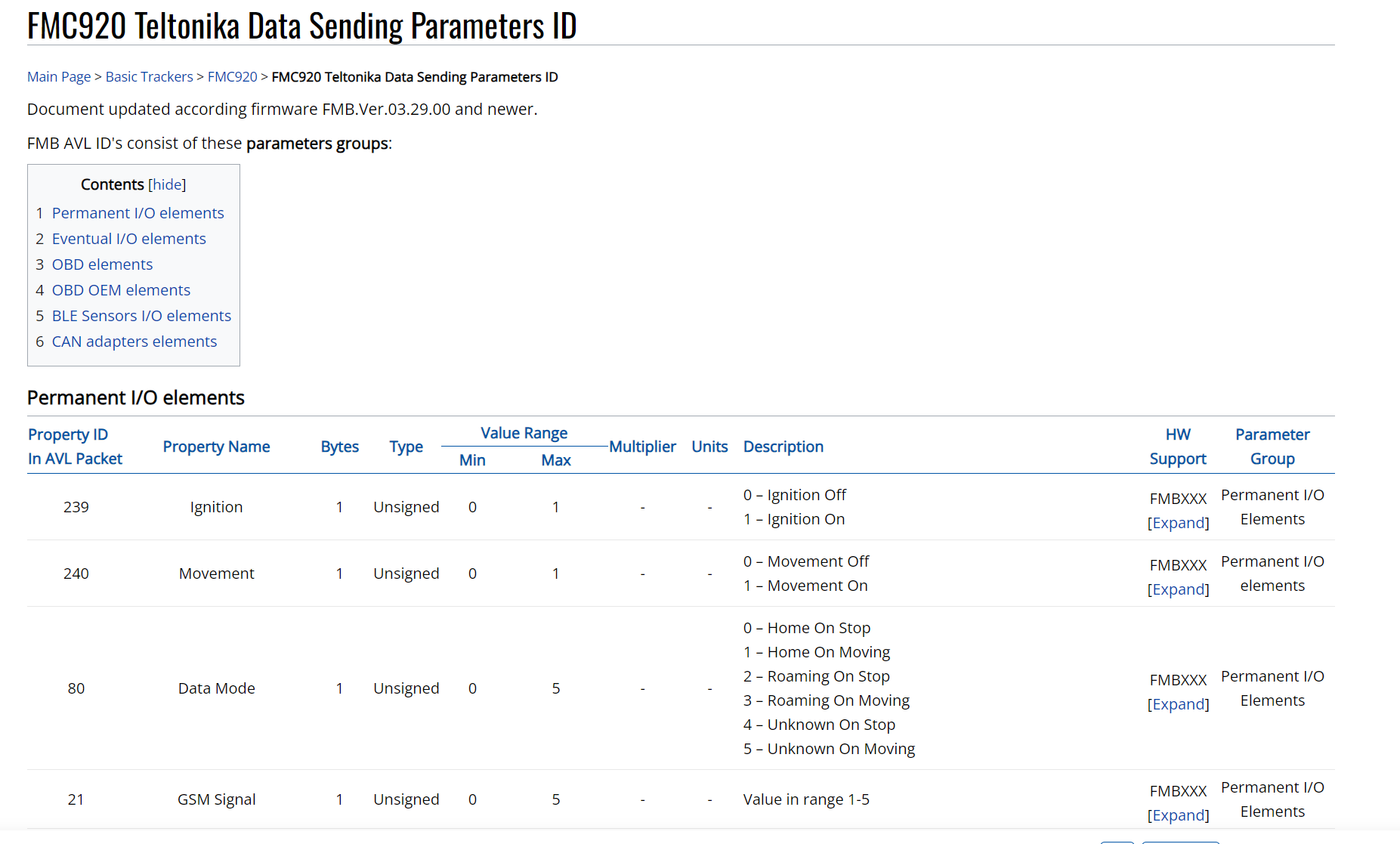
Now we understand the basics of what a sensor needs in order to work and display information correctly, let’s make a custom sensor for battery voltage and ignition state.
One sensor is a value sensor and the other is a logic sensor. These are the two most basic sensors to create but this lays the ground work to create more complex sensors.

Open up your sensor tab in your tracker settings and click the “ADD” (+) button.

Give your sensor a name.
Selects custom under type.
Then what parameter this sensor is reading.
This being the battery voltage, you need to select “io66”

Now select what type of sensor format it is. In this case battery voltage is reading a value, so select “Value”
Now you will need to input “units of measurement”, simply type “Volts”. Now input a formula other wise your sensor will just display what it reads. The raw data from the parameter is “12761”. In order for this to read 12.7 volts the formula will be x/1000

To check is this is correct you can see down the bottom “Current value” this is the raw parameter data. Then on the right “Result”, this show the value after the formula has been added.
Now click “Save” and your all done.
The ignition sensor is a bit simpler as its a logic sensor. This means its will only show a 1 or 0 depending if its ON or OFF.
Open up a new sensors, Input your sensor name, select “custom” and the parameter is io239 for ignition.

Select “Logic” for type and in the section below (if sensor “1” (text) simply type ON or OFF.
In the image example 1=ON and 0=OFF
Click “Save”
For some use cases, the logic sensor using a DIN wire (Digital Input) on the tracker maybe be triggered for a machine fault or similar. For this use case you could type 1=Fault and 0=Working.
The use cases are endless. But keep in mind, the tracker configuration may need to be modified to send through specific data parameters and custom installation or wiring will need to be done so the tracker can see the values from the vehicle or machine.
Sensors with Dictionary’s
Here is an example of a sensor using a dictionary. This is because the io parameter can send though multiple readings. instead of doing a sensor for each value, we can simply create a dictionary so when a certain value is read, it will display a different message.

This is how the dictionary works in this use case.
When the value (0,1,2,4,16) is sent, the sensor will display the corresponding message.
This is a good way to detect faults or or different states of operation.
To find out what each io value represents, you can use the wiki to find the data sending parameter id and it will show what values are sent through.

Triggering an event with alerts
For this example, we will be setting up a low battery voltage event with and alert.
Open up the setting menu on the top tool bar and click on events.

Then click the “ADD” button down the bottom.
Give the event a name
Select what the event is triggered off, in this case we are triggering off a sensor.
Then select what object or tracker this event is for.

The bottom section is essentially a rules dictionary.
Meaning the criteria inputted will have to be met before the event is triggered.
We want our event to trigger when the battery hits 11.8 volts or below. We can do this by selecting the sensor in the drop down menu, in this case we are using the battery voltage sensor we created earlier, then using the below symbol < and entering the parameter value.
Battery voltage < 11.8 volts or simply put
when battery voltage is 11.8v or less, this event will trigger.
Now we can set up the notification for this event.
Select the “Notifications” tab on the top bar and select how you would like to be notified.
System message will display a pop up window on the home page with the details of the event. Tip: make sure you select “Auto hide” other wise the window won’t go away unless you manually close it.
Sound alert will make chime noise when events triggered.
Next you can input a email address or mobile number. if you wish to enter multiple emails or phone number, simply separate each with a comma ,
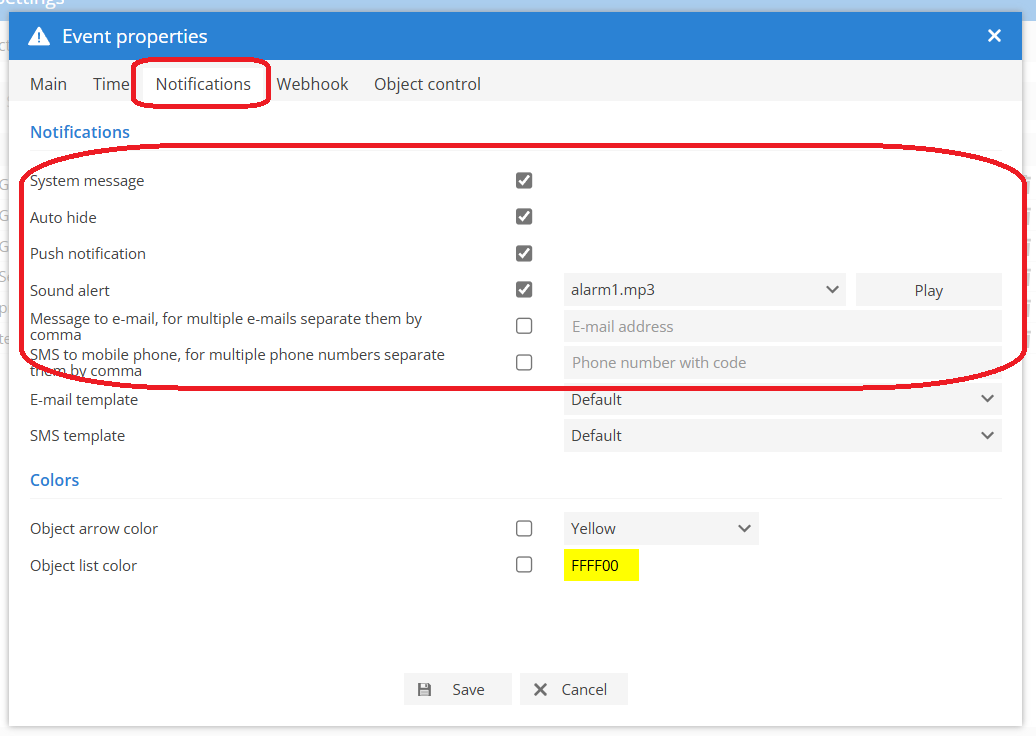
Now click “Save” and your all done.